Beta 2 High Voltage Junction Box (HVJB) //
Beta 2 High Voltage Junction Box (HVJB) //
Sole design engineer of a fully custom High Voltage Junction Box used in our Beta 2 Builds.
This HVJB contains over 50 unique off the shelf parts and 23 custom components. I designed and architected everything from scratch. Everything from the layout, to the busbars, to the billet aluminum panels, to the form factor of the PCB board and its packaging and integration, as well as all the internal harnessing. All this while still meeting all durability and safety requirements.
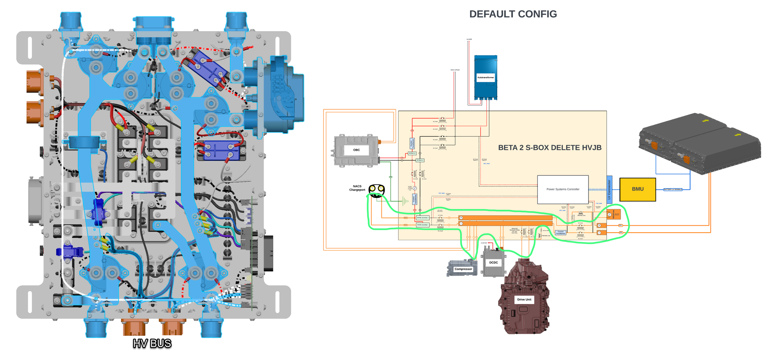
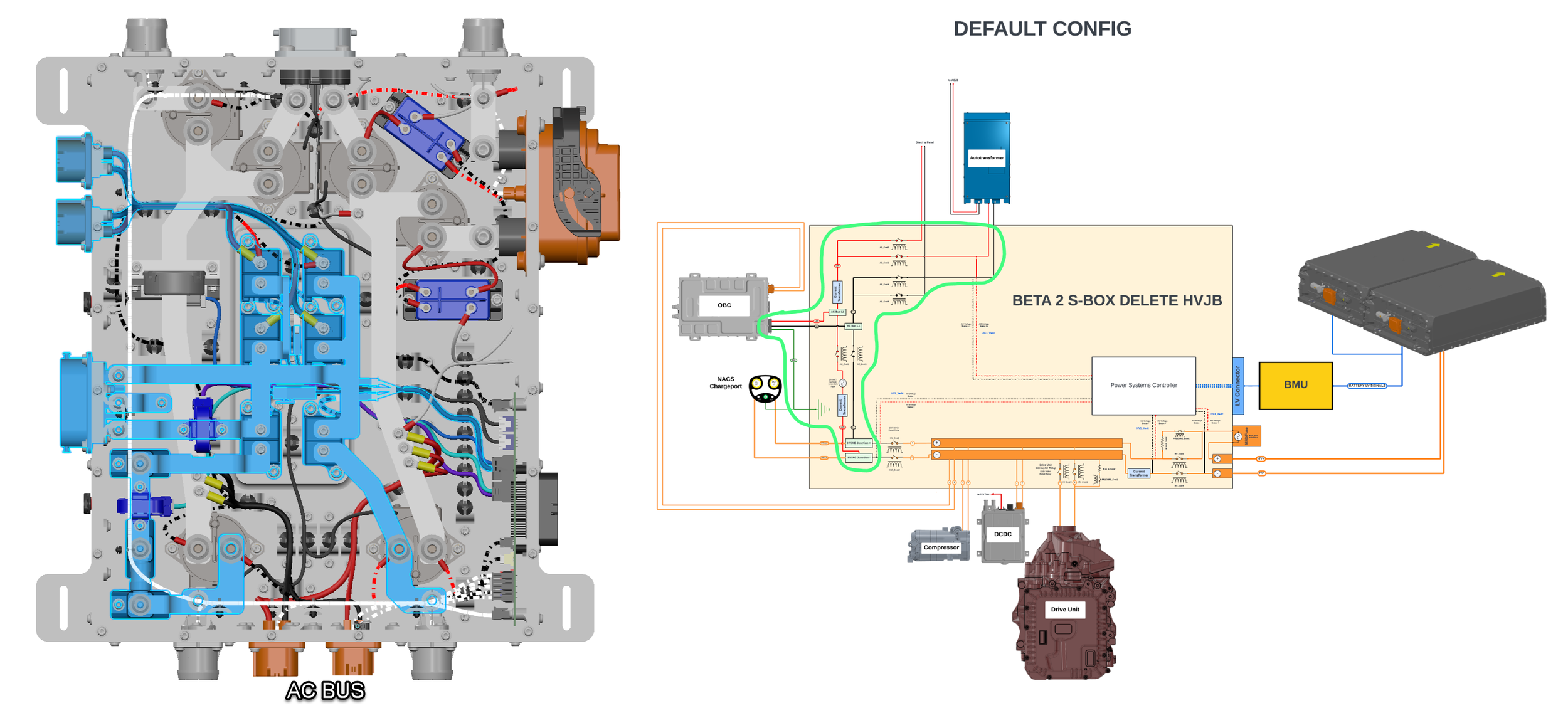
The HVJB facilitates power flow in multiple different scenarios. These are:
HVDC power flowing to the HV battery from various sources, including
From the charge port (DC fast charging)
From the On-board charger (AC charging)
From the 12v DC-DC converter (in boost mode)
From the drive unit (regenerative braking)
HVDC power flowing from the battery pack to various HV components, including:
Drive unit (motoring)
12v DC-DC converter (in buck mode)
OBC (in V2X mode)
HV compressor
HV sensing to check HVDC voltage, and confirm AC vs DC input on NACS charge port
HV isolation check to test HV isolation to ground
Current sensing to determine amperage of current flow (AC and DC)
AC power flow from AC mains (L1/L2 AC connections) to OBC and AC junction box
HV Battery Precharge
Drive Unit Precharge
Manual Service Disconnect (MSD)
Isolation Monitoring
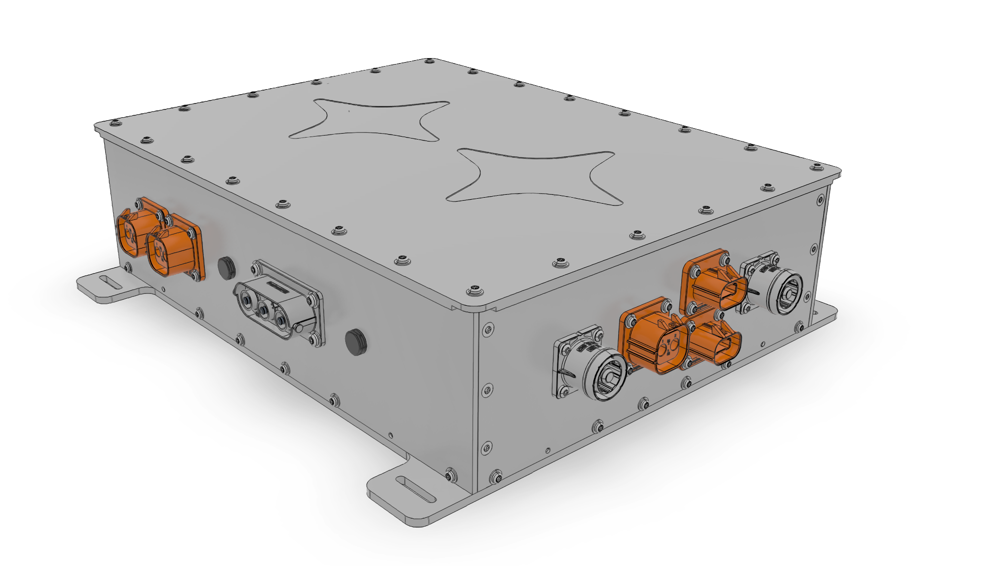
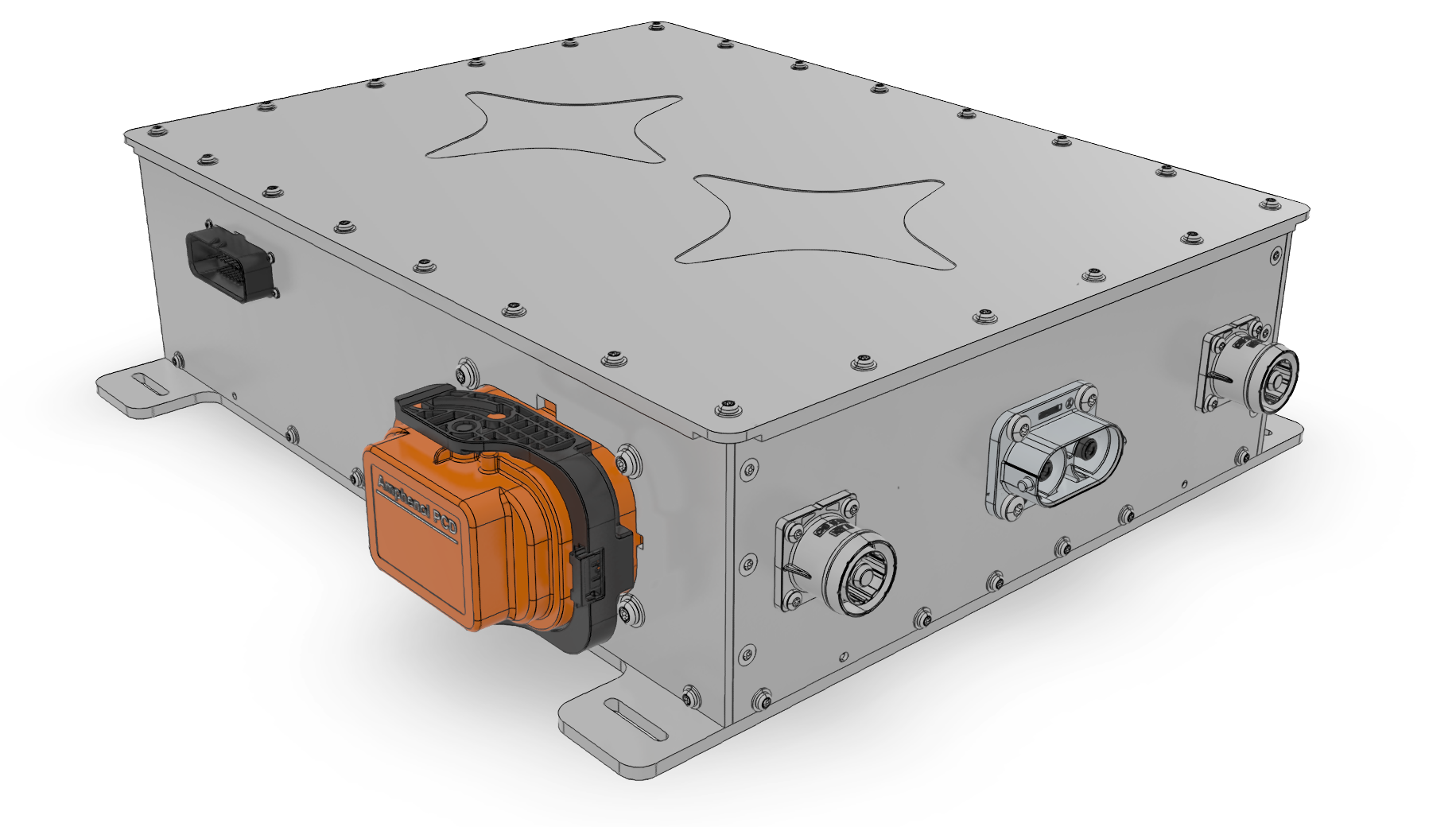
Beta 2 HVJB
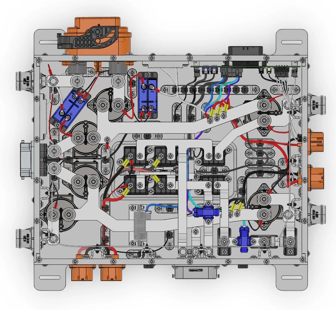
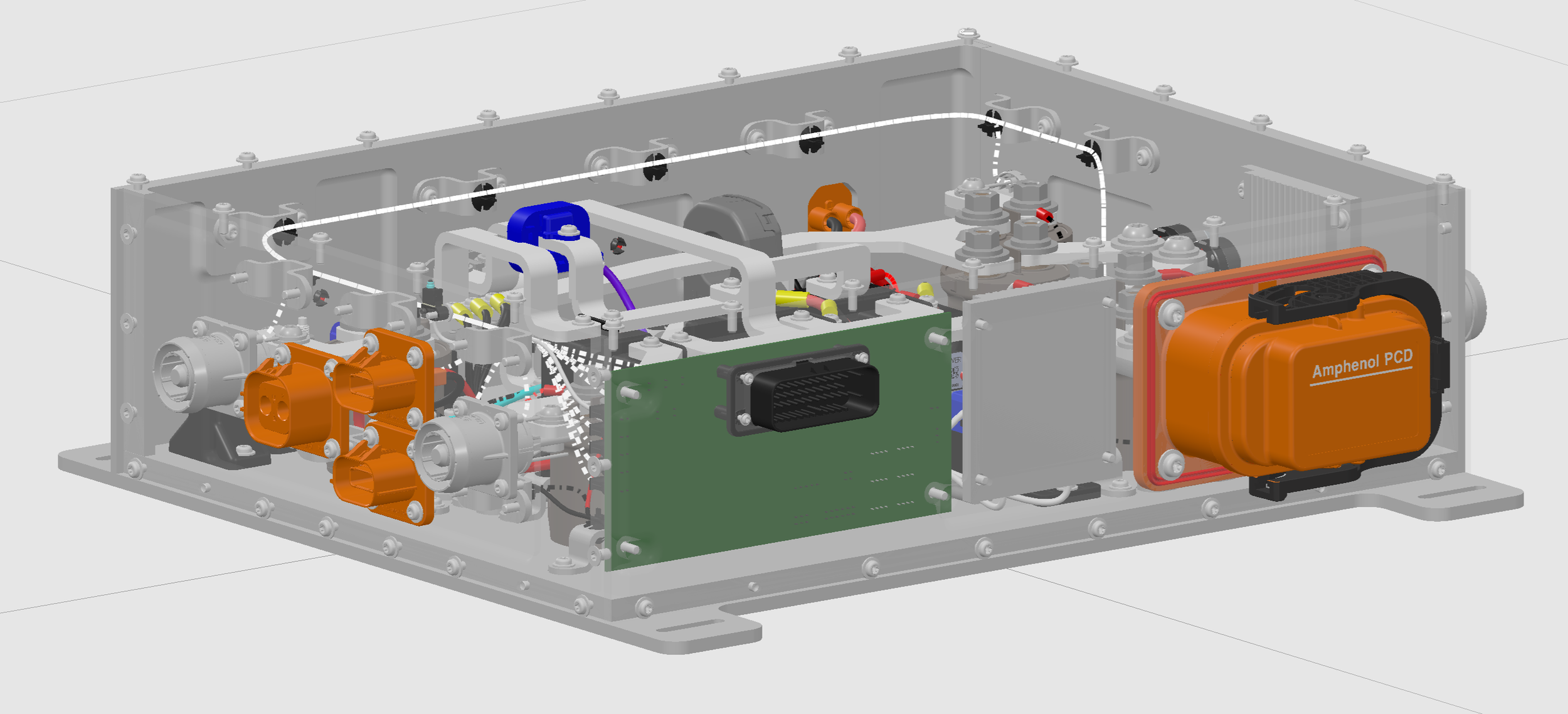
Beta 2 HVJB Internals, conceptualized and executed everything shown here from scratch, including deciding connector locations, bus bar routing, harness routing, component selection etc..
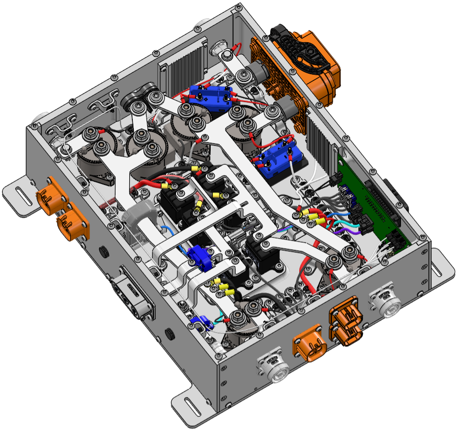
Iso-ish view
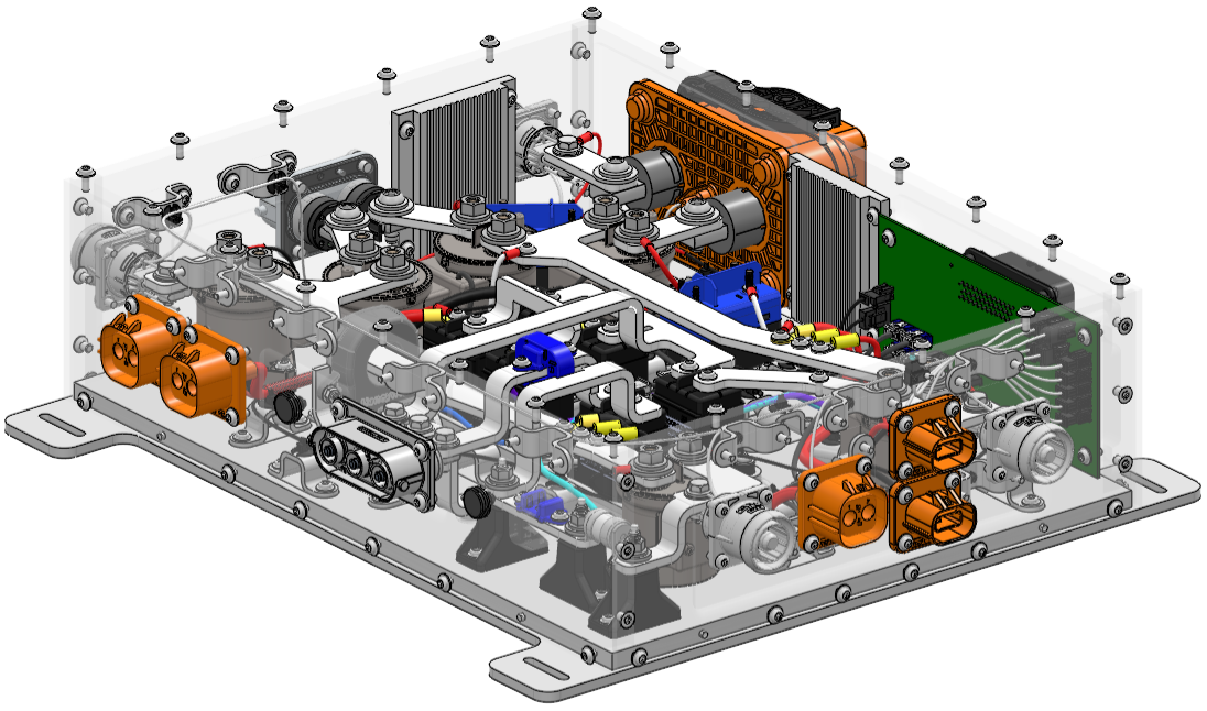
X-ray view, lots of bus bars and harnesses taking different paths
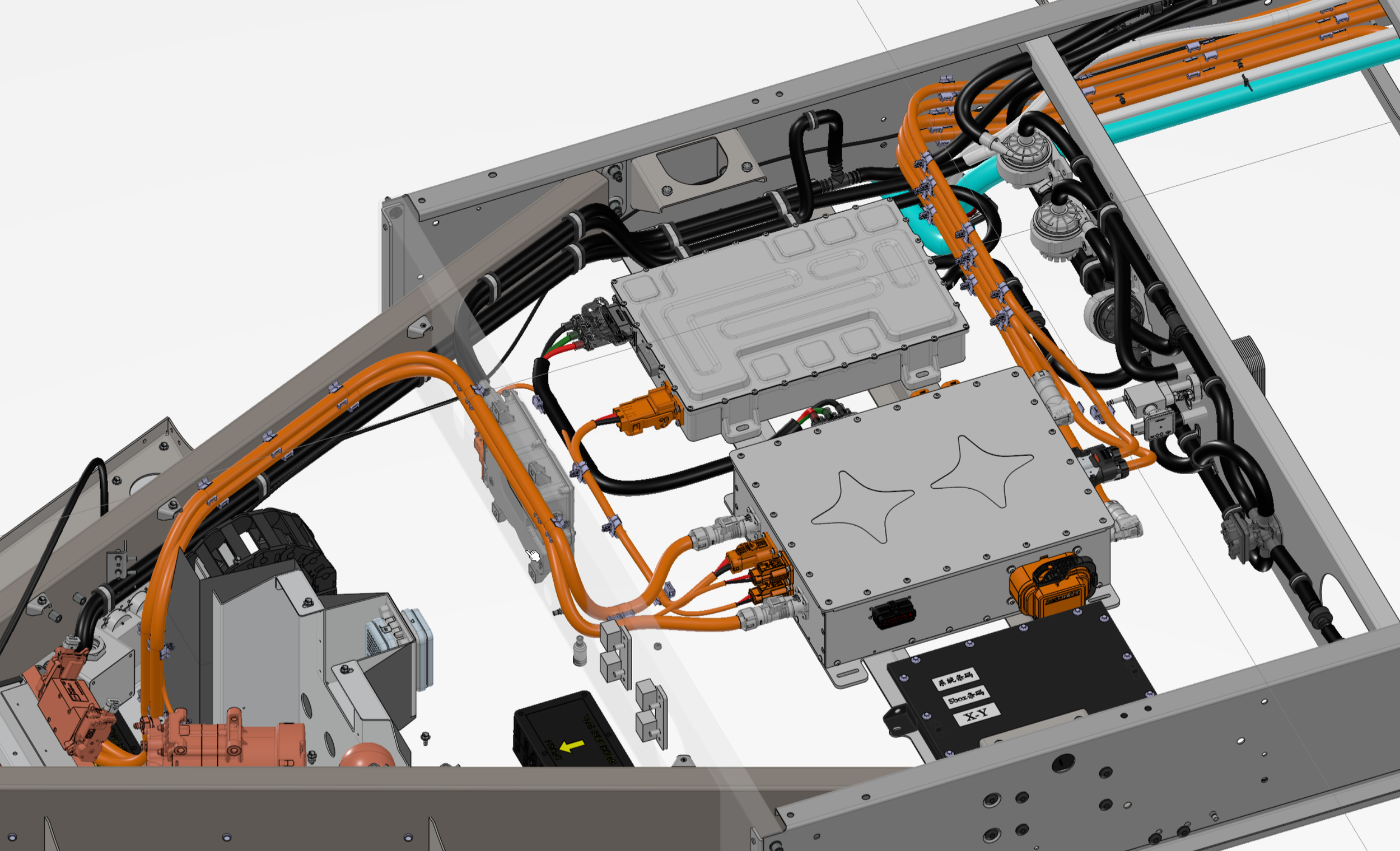
I individually owned and executed the entire underbody of the vehicle in CAD including coming up with the layout and positioning of the power electronics components, routing all the coolant lines and harnessing in CAD, positioning the thermal components and pumps, and ensuring proper retention features along the frame.
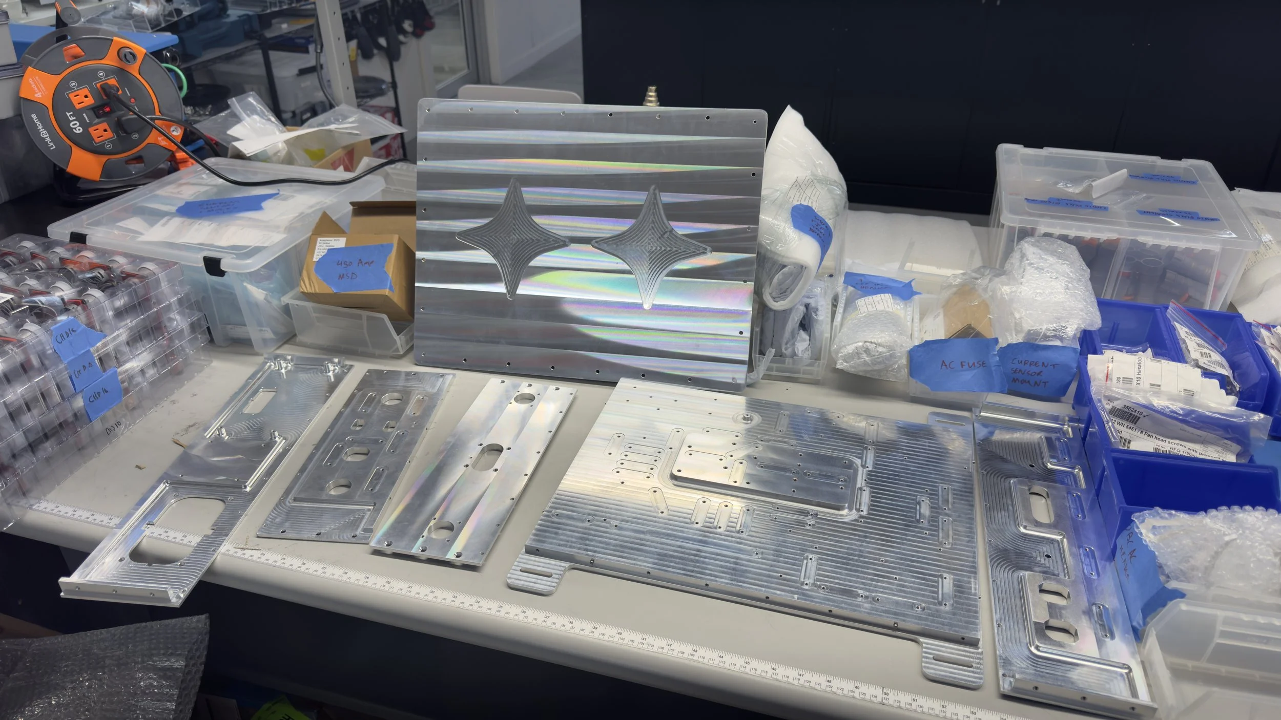
Parts came in!
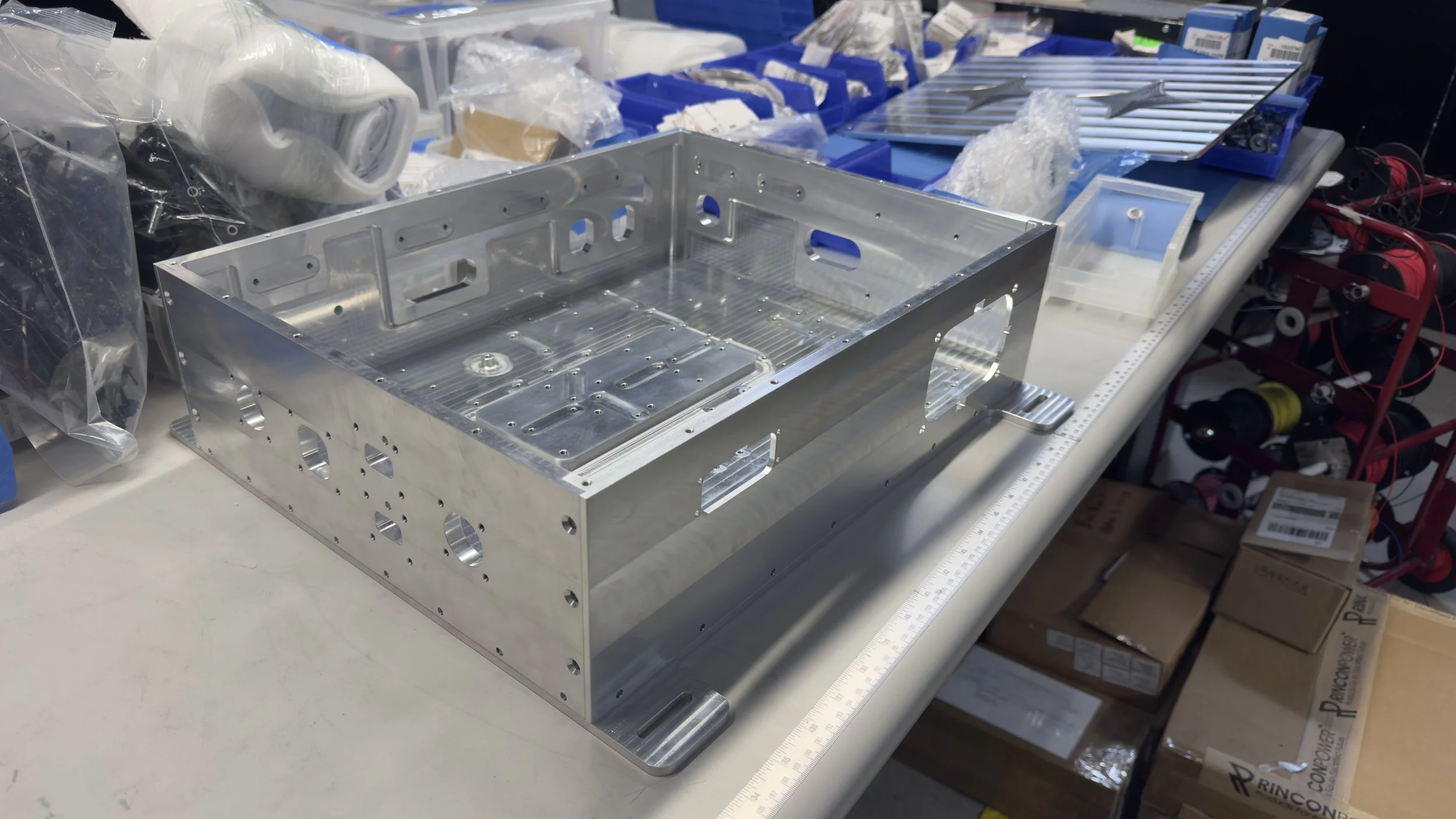
Quick fit check of the cnc'd panels, perfect fit!
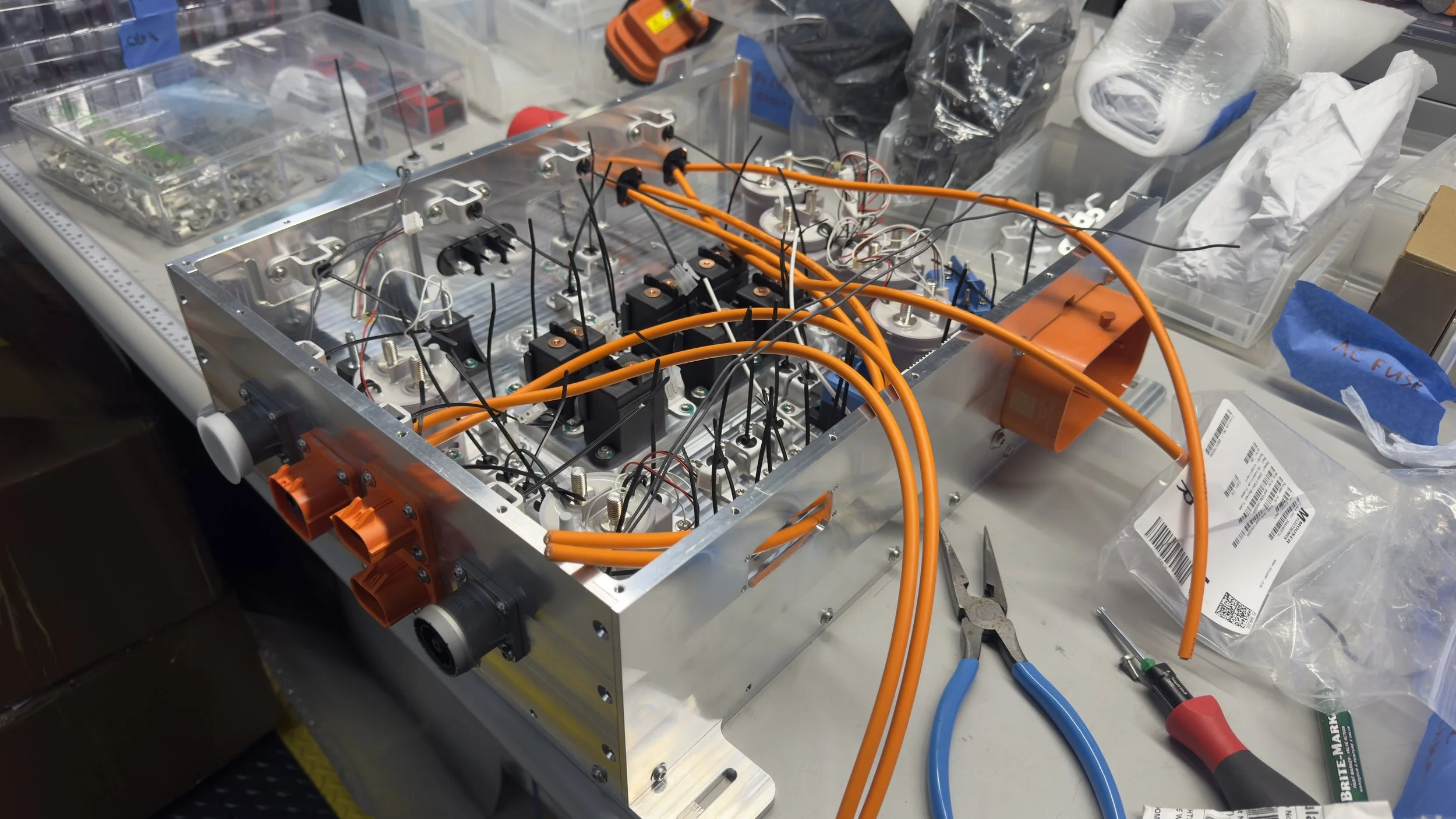
Wiring things up!
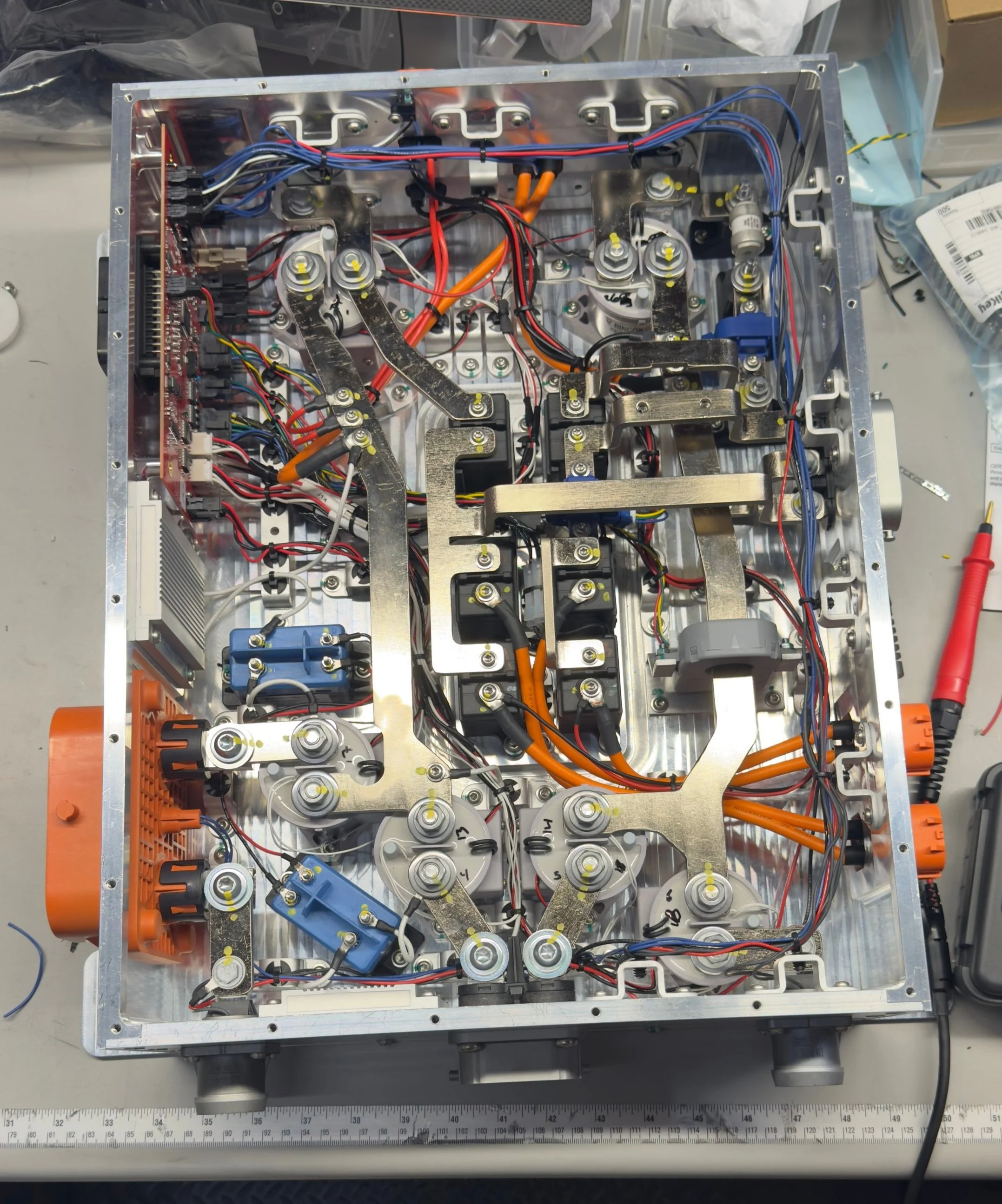
Better view of the HVJB fully wired up!
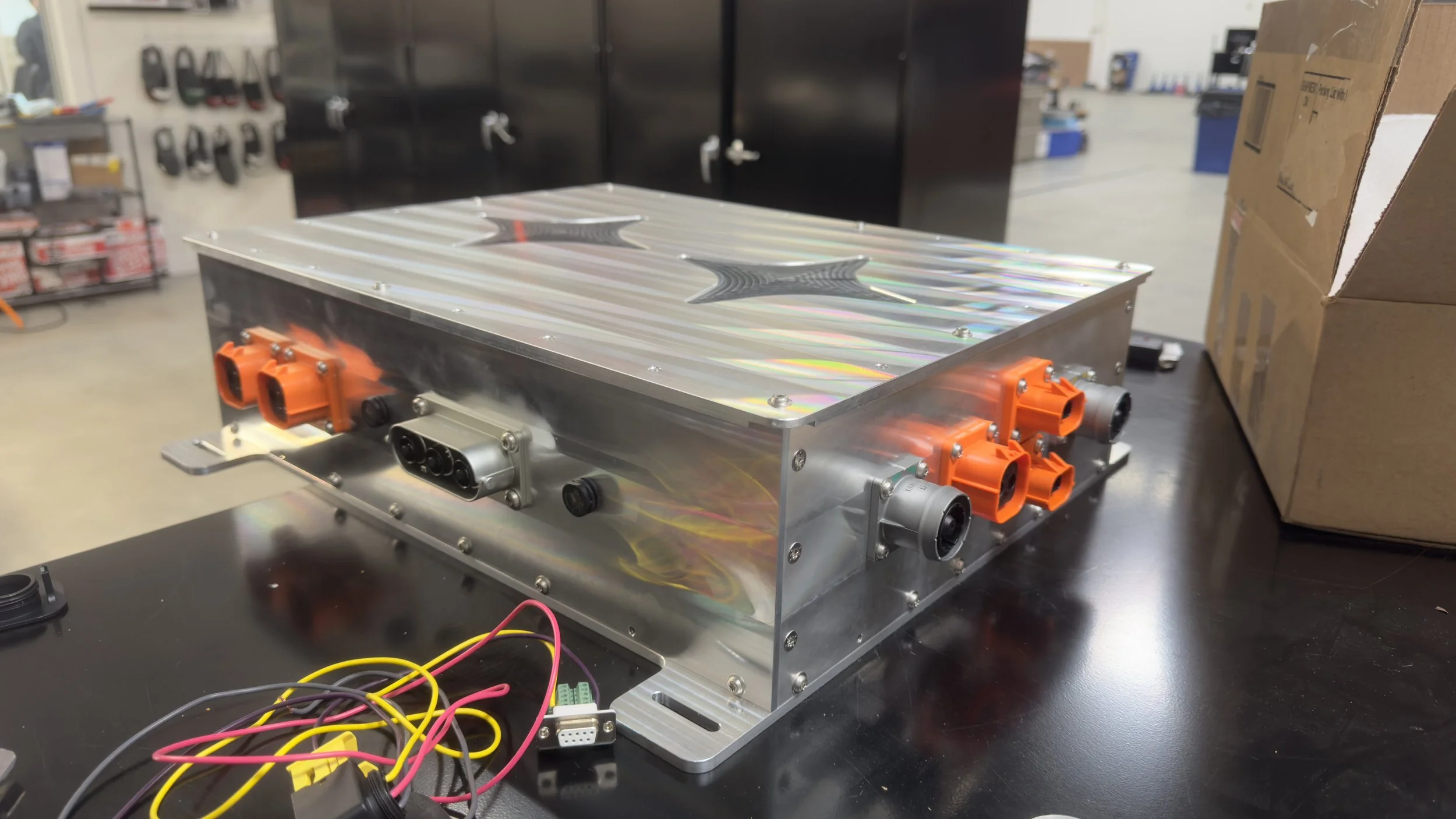
Fully assembled!
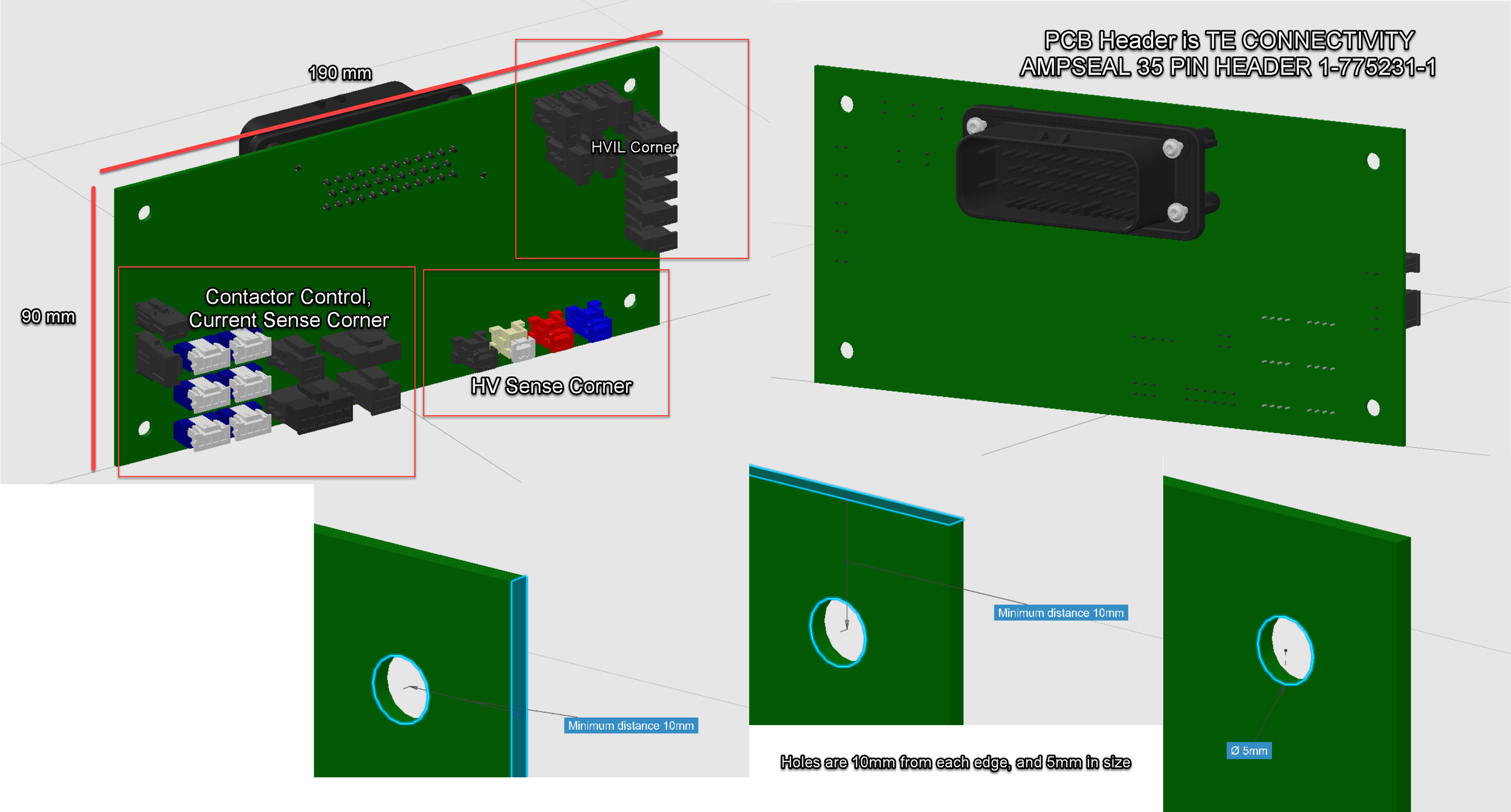
I created a starting point for the board that our electrical engineers could work off of.
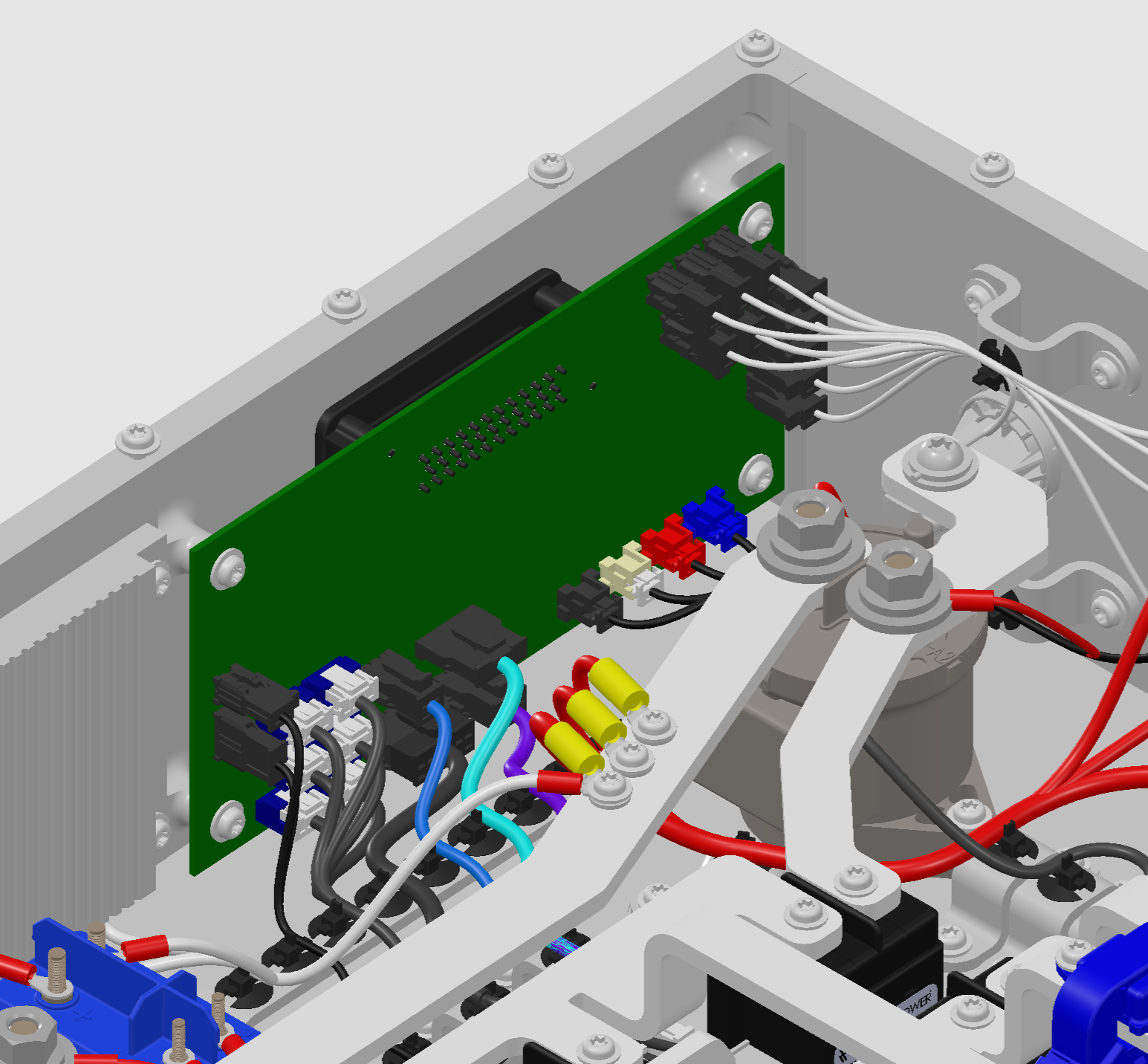
Board is panel mounted, connectors for things like the relays, current sensors, contactors, HVIL, etc plug into the back side,
X-Ray view
HV Bus
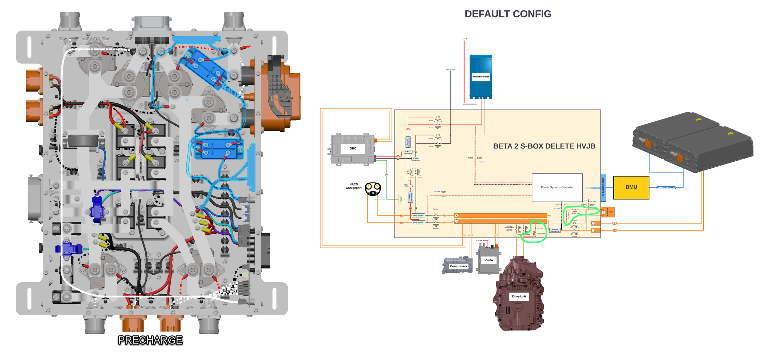
Precharge circuitry
AC Bus
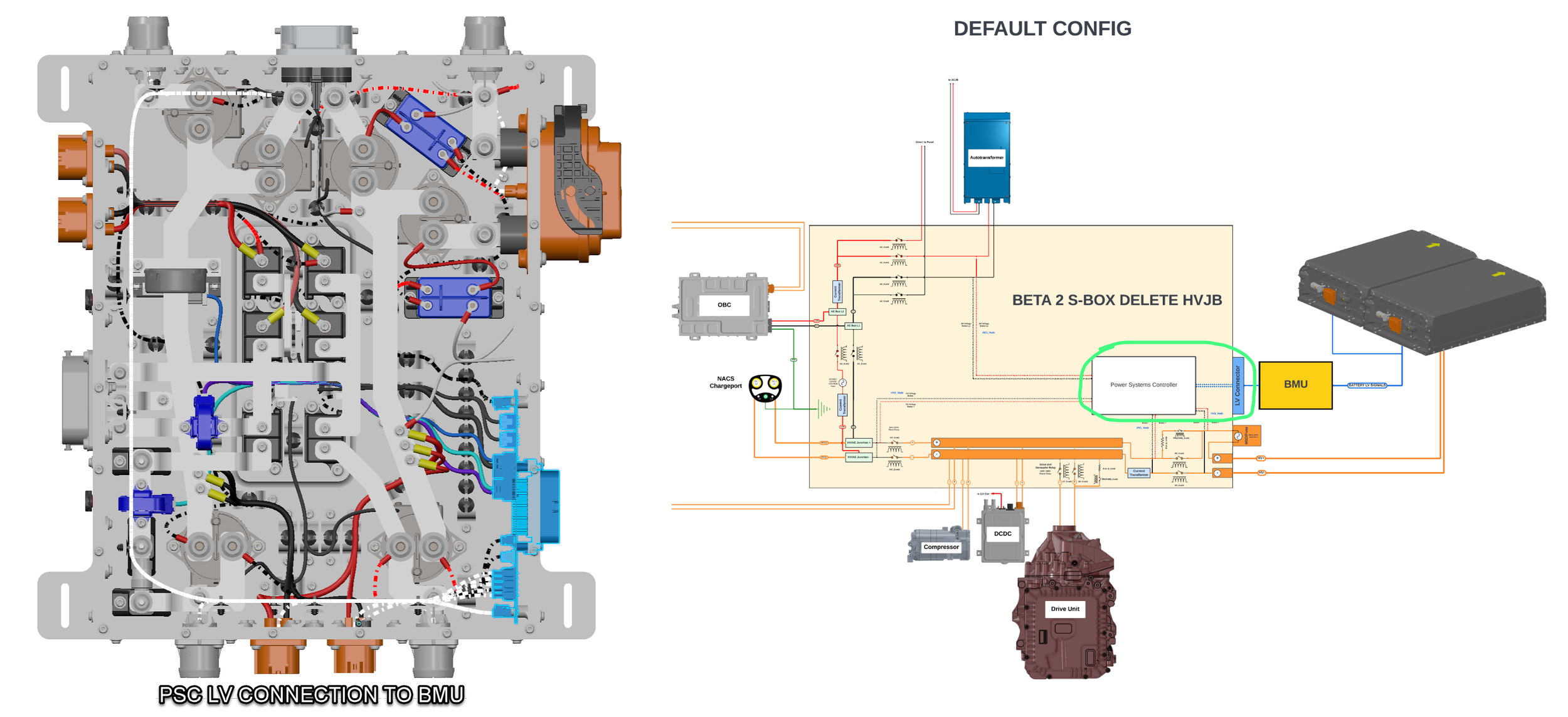
The power systems controller
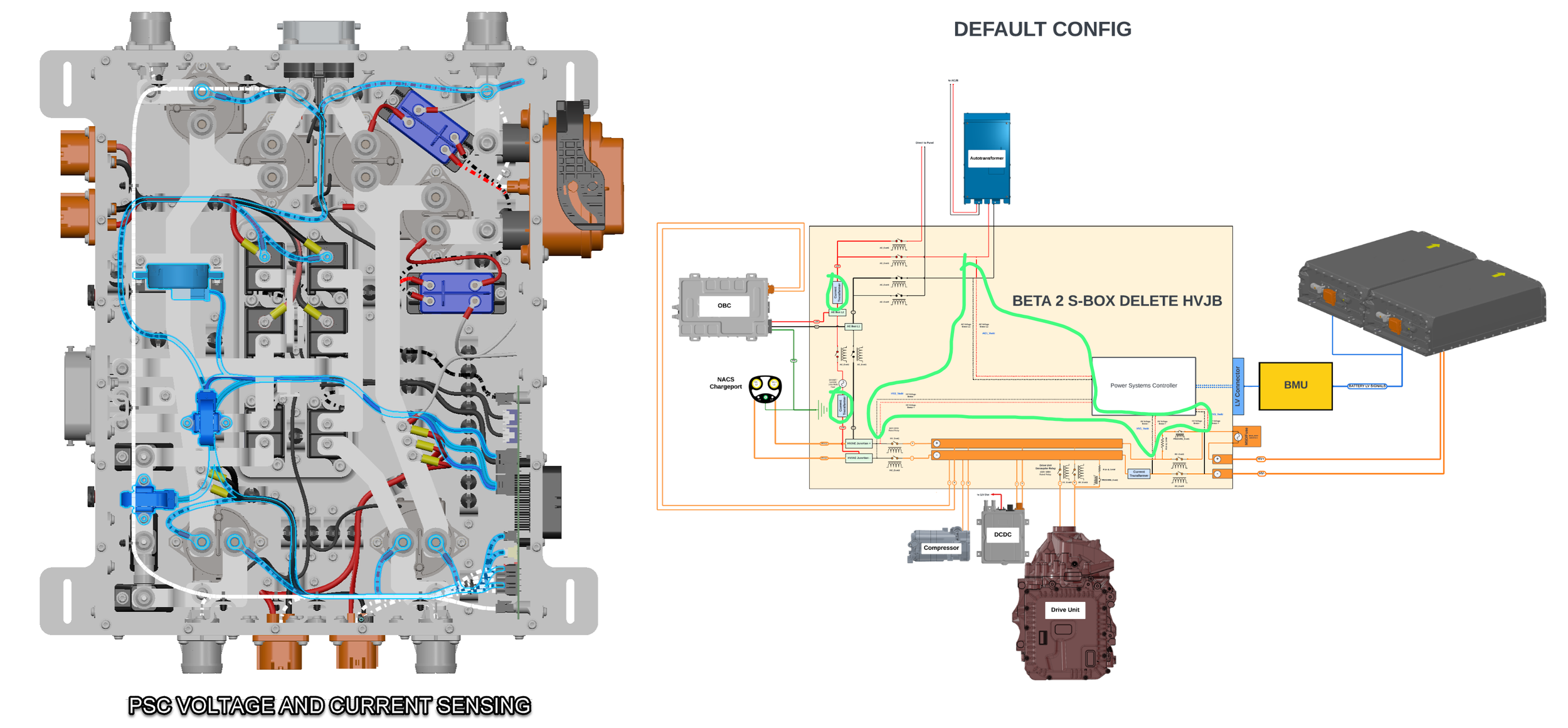
Current and voltage sensing
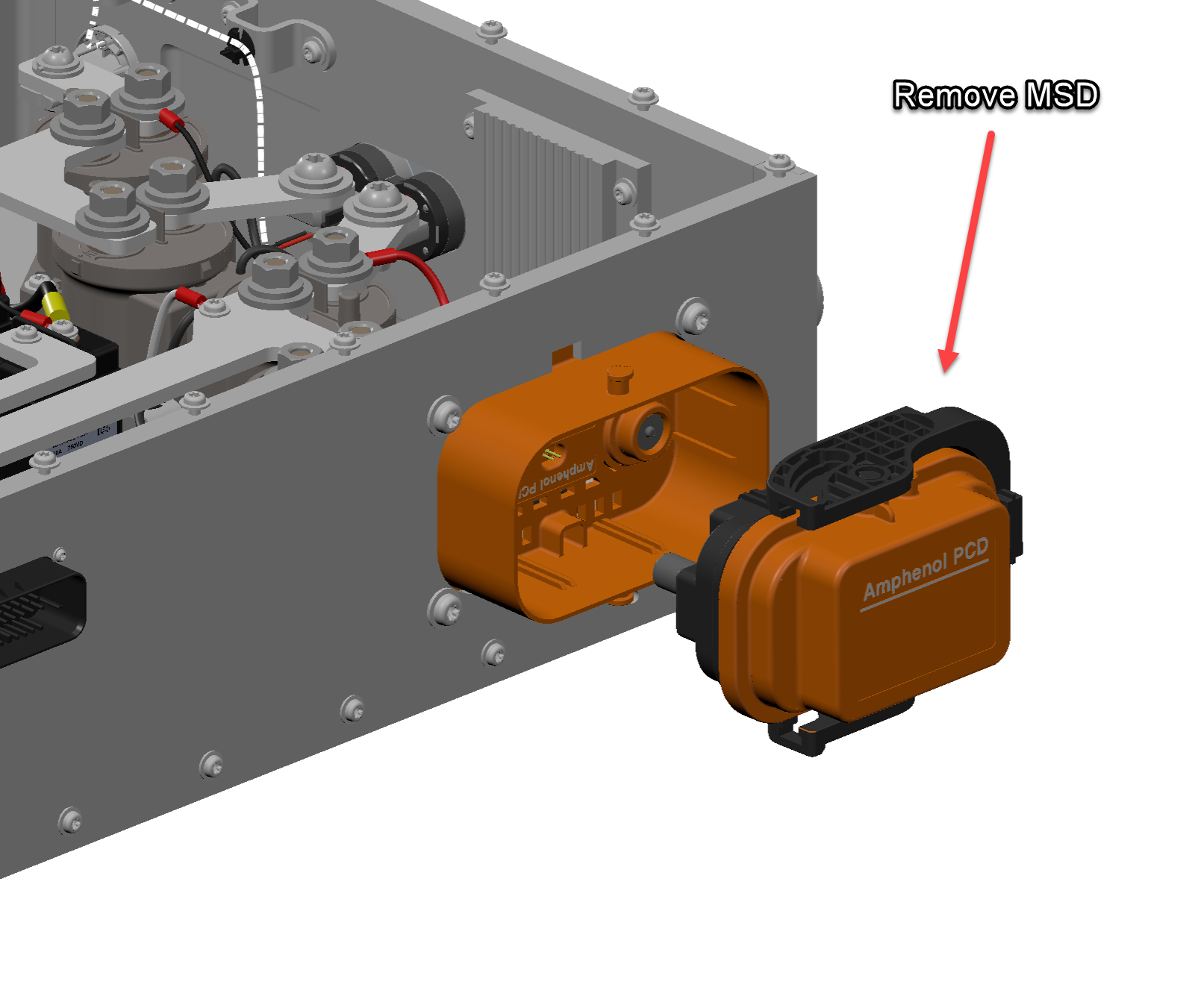
The HVJB included a MSD (Manual Service Disconnect)
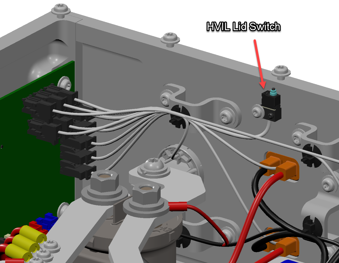
I also added in a lid switch that would make or break HVIL so that the system would automatically shut down if the lid is opened or if it was being serviced